

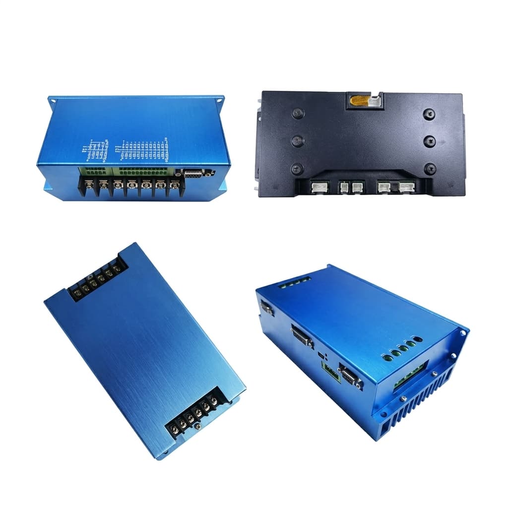
Dual-Absolute Encoders in GaN Servo Actuators: Motor vs. Joint-Side Feedback, Mitigating 50V/ns dv/dt on BiSS-C/SSI, Harmonic Compliance, and Robotics Sourcing
Compare dual-absolute encoders in GaN servo actuators: BiSS-C/SSI noise, motor vs. joint feedback, gear compliance, and an RFQ checklist. Plan your review.
Dual-absolute encoders in GaN servo actuators separate two jobs: measuring the rotor for motor commutation and measuring the joint output after a compliant gearbox. A second encoder is useful when the output-position error budget cannot tolerate gear windup, hysteresis, or transmission error. A single motor encoder can still be adequate for stiff transmissions, direct drives, or less demanding motion tasks; the architecture should follow the required accuracy under load.
An integrated Gallium Nitride (GaN) inverter also places fast switching nodes near feedback electronics. A 50 V/ns edge is a design scenario to evaluate, rather than a property of every GaN drive. Differential signaling, controlled return paths, appropriate error handling, and stable loop tuning must work together; neither a second sensor nor a protocol name establishes system robustness.
Executive Summary (TL;DR)
- Use motor feedback for rotor commutation and velocity estimation, and output feedback to observe gear deflection at the joint flange. Neither sensor alone measures tool-tip accuracy.
- For an assumed 15 pF coupling path and 60 V/ns edge, i = C × dv/dt gives a 0.90 A transient. This screening calculation is not a measured encoder current or fault prediction.
- Compare BiSS-C and SSI implementations by frame integrity, sample age, cable timing, and fault response. A nominal 10 MHz clock does not establish end-to-end latency.
- Identify mechanical modes before raising output-loop gain. Sampling frequency, closed-loop bandwidth, and PWM frequency are separate specifications.
- Use the eight-point RFQ checklist to request traceable waveform, timing, accuracy, and fault-handling evidence for the actual actuator configuration.
Published and reviewed: November 11, 2026. Scope: An engineering and procurement guide for robotics OEMs and sourcing teams evaluating 24V to 60V DC integrated GaN servo actuators for global programs. The worked mechanical example uses a 100:1 strain-wave reducer. Each candidate still needs its own bus-voltage, thermal, cable, payload, and environmental qualification.
Evidence and calculation limits: This is an analytical selection guide, not a report of hardware tests. Numerical examples are hypothetical and reproducible from their stated inputs. They do not establish supplier performance, functional safety, regulatory approval, or medical suitability. Manufacturer sources below support interface and layout principles; the calculations and RFQ criteria are engineering screening proposals. No fixed accuracy, EMI immunity, or settling-time improvement is promised.
Evaluating packaging for a robotic joint? Review our 24V Driver Encoder Servo Stack or Compact Robotic Actuator Controller Board, then contact our engineering team with your feedback requirements. These pages provide integration starting points; confirm dual-channel support and the permitted bus voltage for the quoted hardware revision.
1. Motor-Side vs. Joint-Side Feedback: When Two Encoders Help
In traditional industrial automation, servo motors often mount a single optical or magnetic encoder directly on the rotor shaft. In stiff, direct-drive applications or systems with modest output-position requirements, this architecture works well. A high-ratio reducer changes the question: how accurately does rotor angle represent the loaded output flange?
Strain-wave and cycloidal reducers offer compact torque transmission, but finite stiffness, hysteresis, and lost motion remain selection considerations. A nominally zero-backlash gear is not infinitely stiff. Output feedback observes the flange within its mounting datum; deformation in downstream bearings, links, and tools can remain unmeasured.
The Two-Mass Spring System
A useful first approximation is a motor inertia connected through a gear ratio and an elastic transmission to the load:
[Motor: J_m] -- [Ratio N; output-side stiffness K_g, damping D_g] -- [Load: J_l]
      |                                                                 |
 Motor encoder                                                   Output encoder
 Commutation and velocity                                      Flange position
Here, J_m is motor inertia in kg·m², J_l is load inertia referred to the output in kg·m², K_g is output-side torsional stiffness in N·m/rad, and N is the reduction ratio. Assume a positive, consistent angle convention and calibrated zeros. Under quasi-static loading, neglecting friction and transmission error:
Delta_theta = theta_motor / N - theta_link = Torque_load / K_gWorked example: With a hypothetical 100 N·m output load and 15,000 N·m/rad stiffness, deflection is 0.00667 rad, or approximately 0.382°. At a perpendicular 0.5 m lever arm, the small-angle displacement is about 3.33 mm. This illustrates why adding motor-side counts cannot observe output windup. It does not predict an actual robot's tool-center-point error; pose, structural compliance, and calibration also matter.
Functional Partitioning and Evidence to Request
| Selection question | Motor-side encoder | Joint-side encoder |
|---|---|---|
| Primary job | Rotor commutation and motor velocity estimation | Output-flange position and transmission-error observation |
| Position reference | Rotor angle before the reducer | Flange angle after the reducer |
| Gear compliance visibility | Cannot directly observe downstream twist | Observes relative twist when compared with scaled motor angle |
| Resolution selection | Balance commutation, speed estimation, noise, and timing | Start with the loaded output-error budget |
| Accuracy evidence | Angle error versus rotor position, current, speed, and temperature | Installed flange error versus load, runout, and temperature |
| Latency evidence | Sampling instant through angle use in the current controller | Sampling instant through outer-loop update |
| Main integration concern | Stator heat, stray fields, and commutation alignment | Bearing motion, mounting datum, and hollow-shaft packaging |
Resolution and accuracy are different. A 20-bit single-turn word has approximately 1.24 arcseconds per count, but installed error can be much larger. Ask for absolute accuracy, repeatability, interpolation error, and calibration conditions rather than approving a sensor from bit depth alone. Also specify whether absolute position is single-turn or multi-turn: after power loss, a multi-revolution joint may still need retained turn count or a reference procedure.
2. High dv/dt Noise Coupling: Quantify the GaN Proximity Risk
Switching edge speed depends on the transistor, gate drive, load, bus voltage, and layout. At 48V, a 50 V/ns transition corresponds to roughly 0.96 ns if the slope were constant over the full swing. Use suitable probing to establish the waveform instead of inferring slew rate from PWM frequency. EPC's GaN Design Support Center organizes design resources around device selection, layout, thermal management, and measurement; it is not evidence for the performance of a particular actuator.
Capacitive Displacement Current
In a compact joint, coupling can occur between switch-node copper, motor phases, encoder cables, housing, and signal references. A first-order screening model is:
i_displacement(t) = C_coupling × dv/dt

Assumed C_coupling = 15 pF
Assumed edge slew = 60 V/ns
Peak current estimate = 15 × 10^-12 × 60 × 10^9 = 0.90 A
This is a short transient in the assumed coupling path, not 0.90 A of continuous encoder current. The actual path and pulse shape depend on distributed capacitance, inductance, and shielding. An encoder fault cannot be predicted from this number alone.
For another deliberately simplified calculation, if that current changes by 0.90 A in 1 ns through a 5 nH shared return inductance, V = L × di/dt gives 4.5 V. The assumed current rise time is independent of the specified voltage slew. This illustrates sensitivity to return inductance; it is not a measured logic-pin voltage or proof of latch-up. Verify both differential signal quality and common-mode voltage at the receiver during representative switching.
For purchasing decisions, request scope captures with probe location, bandwidth, grounding method, operating point, and hardware revision. A trace taken with the motor disconnected does not qualify a loaded joint. Include regenerative operation and maximum bus tolerance where they are part of the intended duty cycle.
3. BiSS-C vs. SSI: Select an Implementation, Not a Noise Ranking
The BiSS Association interface overview describes clock/data communication, register access, and per-frame line-delay compensation. Device profiles determine data and CRC parameters. For commonly used BiSS-C position profiles, check the encoder's specified status bits and six-bit CRC against the master configuration; do not assume every BiSS data channel has the same format.
| Procurement question | BiSS-C candidate | SSI candidate |
|---|---|---|
| Electrical connection | Commonly differential clock and data; confirm the actual product | Commonly differential clock and data; confirm the actual product |
| Frame integrity | Verify CRC coverage and handling of error/warning status | Verify parity, additional checks, or absence of integrity checks |
| Cable timing | Confirm master delay-compensation capability and limits | Verify permitted clock versus cable delay and encoder timing |
| Configuration access | Register communication may be available during process transfer | Usually a position stream; extra features are vendor-specific |
| Sample age | Obtain conversion, transfer, and controller-consumption timing | Obtain the same complete timing budget |
| Recovery behavior | Specify rejected frames, stale data, retry limits, and timeouts | Specify plausibility checks, stale data, and timeouts |
| Supplier evidence | Exact profile, decoder configuration, and noise-test logs | Exact word format, timing diagram, and noise-test logs |
CRC detects defined error patterns, not every possible corruption, and it does not correct position data. Avoid blanket claims that a short CRC detects all odd-weight errors or proves safe operation. Firmware must reject invalid data and manage sample age explicitly. SSI can be suitable when its actual integrity provisions and system fault detection meet the application requirements; its name alone does not imply inferior electrical immunity.
A Latency Budget That Can Be Reproduced
Consider an assumed 40-clock complete transaction at 10 MHz. Serialization alone takes 40 / 10,000,000 = 4 µs. Sensor conversion, line delay, isolator delay, timeout, controller scheduling, and register consumption add to that budget. A blanket demand for less than 2.5 µs end-to-end latency would conflict with this example unless the architecture uses a documented prediction or pipelining scheme.
Request a timing diagram from the physical sampling instant to angle use, including jitter and the age difference between the two encoders. More channels do not guarantee simultaneous capture. Single-ended SPI can be reasonable within a short, controlled PCB interconnect; there is no universal 50 mm cutoff. Off-board SPI needs deliberate physical-layer engineering, and error checking depends on the sensor's frame format.
4. Hardware Architecture: Isolation, Shielding, and Layout
The diagram shows a possible dual-feedback architecture. Its labels describe functions rather than validated component specifications. On a narrow screen, scroll the diagram horizontally to read both feedback paths.
Conceptual architecture, not a tested GanServo product schematic. Isolation and filtering are selected for the actual ground domains and measured noise paths.
High-CMTI Isolation Where Ground Domains Require It
Galvanic isolation may help across ground domains; it is not automatically required on every encoder channel inside one low-voltage joint. Where isolation is used, select the guaranteed minimum Common-Mode Transient Immunity (CMTI) for both polarities and the intended temperature range. Also budget propagation delay, channel skew, isolated power, and working voltage. Texas Instruments' Digital Isolator Design Guide, sections 3–4, explains component selection and PCB layout considerations.
For unit comparison, 50 V/ns equals 50 kV/µs. A 100–150 kV/µs minimum CMTI rating could provide screening margin if the barrier actually sees that 50 kV/µs transient. This is an example, not a universal requirement for all 48V drives. A switch-node slope is not necessarily the slope across the encoder isolation barrier. Non-isolated receivers instead need their own common-mode operating and absolute-maximum limits checked.
Differential Pairs and Optional Common-Mode Filtering
Route clock and data as controlled differential pairs with short stubs. Match termination to the cable and transceiver recommendations; 120 Ω is a common example, not an automatic value for every harness. Locate receiver termination appropriately, and review both the master-to-encoder clock path and encoder-to-master data path.
A common-mode choke can help a measured noise problem, but its differential insertion loss, parasitic capacitance, imbalance, and effect on edge timing must be checked. Specifying an impedance at 100 MHz alone does not establish suitability for a 10 MHz clock: its edges contain much higher-frequency energy. Compare receiver waveforms and frame faults before accepting the filter.
Stackup, Returns, and Shield Bonds
Keep encoder traces away from switch-node copper and high-current commutation loops. Preserve continuous reference paths and local decoupling; do not route signals across return-plane gaps. Decide chassis and cable-shield bonding from the actual enclosure and EMC plan. Adding a copper shield without a controlled return can redirect displacement current into the sensitive circuit or increase capacitive loading. Respect any genuine isolation barrier rather than bridging it with a ground plane.
5. Control Dynamics: Harmonic Compliance and Two-Mass Resonance
Closing an output-position loop around a compliant transmission changes the mechanical plant seen by the controller. Adding the sensor does not itself make the system stable. Use low-energy commissioning, current limits, and suitable mechanical support while identifying modes.
Two-Mass Screening Calculation
For an ideal undamped model with output-side stiffness K_g, motor inertia reflected to the output is J_motor_out = J_m × N². The motor-coordinate torque-to-position response has an anti-resonance at the first frequency below; the coupled elastic mode has the second frequency:
f_anti = sqrt(K_g / J_l) / (2 × pi)
f_res  = sqrt(K_g × (1 / (J_m × N²) + 1 / J_l)) / (2 × pi)

Assumed K_g = 15,000 N·m/rad
Assumed N = 100; J_m = 0.00005 kg·m²; J_l = 0.8 kg·m²
J_motor_out = 0.5 kg·m²
f_anti ≈ 21.8 Hz
f_res  ≈ 35.1 Hz
The anti-resonance location depends on the measured input/output transfer function; it is not a universal notch in every link-position response. Real stiffness can depend on torque and temperature, while bearings, housings, and payloads add modes. These frequencies identify a region to investigate, not a fixed controller bandwidth or a guaranteed phase margin.
Cascaded Control and Damping
One implementation uses rotor angle for commutation, motor velocity for an inner motion loop, and output position for the outer loop. PWM frequency, current-controller update rate, encoder polling rate, and closed-loop bandwidth must be specified separately. A 100 kHz update rate does not imply a 100 kHz torque bandwidth, and faster GaN switching does not establish a particular position-loop bandwidth.
A velocity-difference damping term can be considered in consistent output-side coordinates:
relative_velocity = omega_motor / N - omega_link
output_referred_torque_correction = -B_active × relative_velocity
The controller must convert this output-referred correction to motor torque and then current using the gear ratio, torque constant, sign convention, and the chosen efficiency model. It cannot simply add torque in N·m to an Iq reference in amperes. Numerical differentiation, filter delay, saturation, quantization, and asynchronous samples can undermine damping. Validate the complete loop with measured frequency response and payload extremes; this formula alone proves neither stability nor a settling-time improvement.
If the supplier cannot demonstrate tuning margins for the proposed payload range, keep approval conditional. Share the inertia range and motion profile when requesting an actuator control integration review, rather than accepting a generic claim of “active damping included.”
6. Sensor Technology Trade-offs: Magnetic vs. Optical vs. Inductive
Choose sensing physics for installed accuracy, packaging, temperature, contamination, and timing. The table gives qualitative selection questions; it does not assign universal resolution, accuracy, cost multiples, or runout tolerances to a sensor family.
| Evaluation dimension | Magnetic encoder | Optical absolute encoder | Inductive encoder |
|---|---|---|---|
| Motor-side use | Check magnet placement and commutation alignment | Check speed capability and disc mounting | Check target geometry and conversion delay |
| Output-side use | Ring geometries can support a hollow shaft | Ring/disc implementations depend on the product | Annular PCB/target designs can support a hollow shaft |
| Accuracy evidence | Installed angle-error map, including calibration | Installed grating/readhead accuracy and alignment | Installed target/readhead accuracy and alignment |
| Stray magnetic fields | Request motor-current and external-field testing | Optical sensing avoids direct magnetic angle measurement; electronics still need EMC qualification | Check external-field and conductive-environment effects for the product |
| Contamination | Verify sealing and effects of metallic debris | Verify optical path protection against grease and condensation | Verify target environment and effects of conductive contamination |
| Runout and air gap | Obtain permitted eccentricity, tilt, and gap | Obtain disc/readhead alignment and gap limits | Obtain target gap, tilt, and runout limits |
| Thermal behavior | Verify magnet, mounting, and electronics drift | Verify mechanics, source, and electronics drift | Verify PCB, target, and electronics drift |
| Lifecycle cost | Include calibration, assembly, and shielding | Include alignment, protection, and service access | Include target manufacture, calibration, and assembly |
For the motor, select sufficient resolution and response for commutation and velocity estimation. Higher bit depth may still benefit smoothness or diagnostics, but cannot remove gearbox windup. For the output, allocate allowable flange error before choosing a technology. Optical sensing is not automatically a qualification for surgical use, and inductive sensing is not universally immune to fields, oil, moisture, or conductive debris. Ask for specifications on the exact installed configuration.
7. The 8-Point Dual-Encoder RFQ Procurement Checklist
Use these questions to create an evidence request before sample approval. Agree numeric acceptance limits with the supplier for the actual motion and environment; the examples are not industry certification thresholds.
- 1. Channel capability and identity: Obtain connector pinouts, voltage levels, supported profiles, hardware/firmware revisions, and channel scheduling. A multiplexed architecture is acceptable only if its worst-case sampling age and jitter meet the agreed requirements. Two sensors do not automatically provide safety-rated redundancy.
- 2. Electrical noise limits: Request guaranteed isolator CMTI where isolation exists, receiver common-mode limits, supply margins, and waveform captures at relevant nodes. State bus tolerance, temperature, cable length, shield bonds, and measured edge slope.
- 3. Communication endurance under switching: Require a per-channel log of total frames, CRC/status/timeouts, consecutive failures, and stale samples during loaded motion and regeneration. As an example, zero detected bad frames in 100 million frames is an observed test result, not a bit-error-rate guarantee. Under independent, constant-rate failure assumptions, its approximate 95% upper bound is three detected bad frames per 100 million frames; correlated PWM noise and undetected errors need separate treatment.
- 4. Complete timing budget: Obtain physical sample-to-controller-use latency, worst-case jitter, frame length, clock rate, conversion delay, and encoder-to-encoder skew. Check arithmetic against the transaction length before accepting a microsecond claim.
- 5. Control validation and fault handling: Request payload-dependent frequency responses, tuning limits, saturation behavior, and a demonstrated response to missing or implausible feedback. Coordinate vertical-axis stopping and brake engagement at machine level; do not prescribe an immediate inverter trip as a universal safe response.
- 6. Gear and encoder calibration: Obtain the calibration method, residual error under both torque directions, temperature/load conditions, and storage/version controls. A look-up table can reduce repeatable error; it cannot eliminate arbitrary hysteresis or structural compliance.
- 7. Installed sensing immunity: Require angle-error checks with representative motor current, temperature, external fields, and contamination. Separate interface packet integrity from sensor accuracy: correct CRC can accompany an incorrect physical angle.
- 8. Mechanical and production acceptance: Specify runout, gap, bearing motion, thermal drift, single/multi-turn recovery, traceability, end-of-line tests, change notification, and requalification triggers for replaced sensors, cables, power stages, or firmware.
Keep raw logs and the agreed test configuration with the sample approval record. Repeat the relevant qualification when a change affects the signal path or mechanical datum. This turns an RFQ response into a usable production acceptance baseline.
8. Frequently Asked Questions (FAQ)
Q1: Why not increase motor encoder resolution instead of adding a second encoder?
More motor-side counts can improve quantization and velocity estimation, but cannot directly measure deformation after the reducer. Add output feedback when loaded flange accuracy requires that observation. Keep single feedback where its complete error budget is adequate; tool accuracy still depends on downstream mechanics.
Q2: What should happen if a GaN transient corrupts a BiSS-C frame?
Reject a detected invalid sample and track its age. Whether the controller may briefly predict position, hold a command, or execute a controlled stop depends on the machine risk assessment and validated firmware behavior. Repeated failures need a defined escalation and brake sequence where applicable. Ordinary BiSS-C CRC handling is not a functional-safety certification.
Q3: Is SPI unsuitable for every encoder connection?
No. SPI can suit a controlled on-board connection, and some sensor formats include their own CRC. An unbuffered single-ended cable near motor phases presents additional signal-integrity challenges. Evaluate electrical buffering, cable geometry, timing, and frame checks rather than applying a universal cable-length prohibition.
Q4: Can BiSS-C run at 10 MHz through a robotic arm harness?
Possibly, if the encoder, master, transceivers, delay compensation, cable, and complete timing budget support it. Verify receiver waveforms and frame logs at maximum harness length and worst operating conditions. Lowering the clock may improve margin but also increases sample age; no single capacitance or termination value guarantees success.
Q5: How does gear compliance affect loop tuning?
It introduces elastic modes that can limit output-loop gain and bandwidth. Identify the modes across the intended payload range, then evaluate gain separation, filters, observers, or damping with measured stability margins. Neither a high current-loop update rate nor the presence of two encoders guarantees a stable joint.
Q6: How should magnetic sensor interference be checked?
Measure installed angle error across rotor position and representative current vectors, including temperature extremes. Shielding, differential sensing, relocation, or compensation may help, but their effectiveness is product-specific. A calibration at one holding-current condition cannot establish immunity across all current directions, field gradients, or operating states.
9. Conclusion & Actionable Next Steps
Dual-absolute feedback can make gearbox deflection observable and improve loaded output control when the mechanical error budget justifies it. GaN integration adds a signal-integrity task that must be qualified with the same care as thermal and mechanical fit. Choose the feedback architecture from accuracy and timing requirements, then use measurements to qualify noise margins and control stability.
For packaging, compare the 24V Driver Encoder Servo Stack with the Compact Robotic Actuator Controller Board. Confirm the required encoder channels and bus envelope before selecting either integration path; the links are not evidence of a standard dual-BiSS-C feature.
To start a technical discussion, send your actuator requirements to our application team: motor winding data, bus minimum/maximum, current and duty cycle, gear ratio and stiffness, payload inertia range, accuracy target, encoder profiles, harness length, enclosure constraints, and expected volume. Request a configuration-specific proposal and validation plan before committing to sample or production acceptance.
10. Sources & Reference Limits
Sources checked for this review on November 11, 2026:
- BiSS Association e.V. — BiSS Interface. Official overview of topology, frame features, line-delay compensation, and profile-dependent data channels. Obtain the selected encoder's exact profile and timing specification separately.
- Texas Instruments — Digital Isolator Design Guide. The checked PDF identifies itself as SLLA284G, revised September 2023, despite the older URL suffix. Sections 3–4 cover isolator selection and layout; this guide does not certify an actuator or prescribe one encoder-channel CMTI threshold.
- Efficient Power Conversion — GaN Design Support Center for EPC Products. The checked URL serves a design-support index covering layout, thermal management, and measurement resources. It does not substantiate a particular joint's efficiency, slew rate, or settling performance.
Author
Categories
More Posts
Thermal Management Strategies for Micro GaN Servo Drives in Robotic Joints
Actionable stack-up and firmware strategies for managing heat dissipation in ultra-compact GaN-based servo PCBA stacks for humanoid robots and cobots.

Managing EMI/EMC Compliance in High-Frequency GaN Servo Drives for Mobile Robotics
GaN servo EMI/EMC guide for robotics teams: specify 48V drives, review PCB layout, gate shaping, SSFM, and vendor evidence before CE/FCC compliance testing.
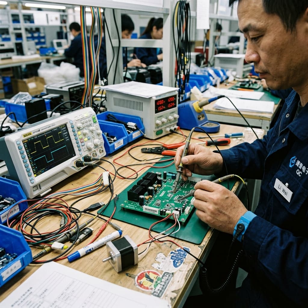
Supplier Validation Checklist: Qualifying an OEM for Robotic Joint Electronics
Hard data thresholds for hardware engineering and procurement teams to evaluate electronics manufacturing partners for critical robotic actuators.