

IEC 61800-5-2 STO in GaN Servo Drives: The B2B Robotics Procurement & Architecture Guide
Evaluate IEC 61800-5-2 STO in GaN servo drives: compare safety architectures, check OSSD and braking limits, and prepare an evidence-based robotics RFQ.
IEC 61800-5-2 Safe Torque Off (STO) inhibits torque-producing drive output; it does not provide electrical isolation, a controlled stop, or a mechanical holding brake. For robotics procurement, start with the required safety function and risk assessment, then qualify the exact drive, safety manual, and integration conditions. GaN power density alone establishes no safety integrity level.
Executive Summary (TL;DR)
- Specify the required PLr or SIL for each safety function; neither GaN technology nor EU Regulation 2023/1230 creates a universal SIL 3 / PL e requirement.
- Compare external contactor and integrated STO architectures using the complete safety chain, including diagnostics, stopping behavior, and service isolation.
- Match CMTI, gate safe states, and OSSD test-pulse tolerance to the selected devices and measured system conditions rather than generic numerical thresholds.
- For gravity-loaded axes, assess controlled stopping and load holding separately; STO alone cannot prevent a dropped load.
- Approve a supplier only after reviewing the exact model and revision, safety evidence, response-time limits, and machine-level validation responsibilities.
Reviewed: October 26, 2026. Scope: An English-language procurement and architecture guide for global robotics OEMs evaluating nominal 24–60 V DC GaN servo boards for AMRs, AGVs, and industrial robot joints. The EU discussion applies to machinery placed on the EU market; other markets need their own conformity assessment. This guide does not cover medical-device approval, complete robot certification, or detailed circuit qualification.
Method and evidence limits: The comparison below is an engineering screening framework, not a laboratory benchmark or customer case study. Numerical examples are explicitly hypothetical. No GAN Servo product certificate, measured savings, or tested STO circuit is established by this article. Normative requirements must be checked against the applicable editions of the standards and the selected product's safety manual.
Preparing an RFQ? Compare your envelope and DC-bus requirements with our 48V bare-board GaN servo driver or 24V custom motor control PCBA platform, then send the engineering team your safety requirements. Request model-specific safety evidence before treating any offered board as an approved safety subsystem.
1. Regulatory Scope: EU Machinery Regulation and ISO 13849-1
Regulation (EU) 2023/1230 generally applies from January 20, 2027, with some provisions applying on other dates. It replaces the Machinery Directive framework. It does not require every robot drive to provide SIL 3 / PL e STO, and fitting an STO drive does not establish machine conformity. Determine the relevant machinery category, conformity route, transition provisions, and safety functions for the actual machine.
ISO 13849-1:2023 provides a methodology for designing and integrating safety-related control systems. Its scope explicitly does not prescribe the safety functions or required performance levels for particular applications. Procurement should obtain the machine risk assessment and applicable machinery-specific requirements before setting PLr or SIL targets.
What IEC 61800-5-2 STO does
IEC 61800-5-2:2016 addresses functional safety of adjustable-speed drive systems. STO prevents the drive from supplying energy that can generate torque. It can implement the torque-removal part of an uncontrolled stop, commonly described as stop category 0. The DC link can remain live, external forces can move the axis, and fault-related residual motion must be addressed by the safety manual.
For an RFQ, record the target safety function, required PLr or SIL, declared dangerous-failure probability, mission time, diagnostic assumptions, proof-test requirements if applicable, and permitted installation conditions. PL, architecture category, SIL, diagnostic coverage, and hardware fault tolerance are related assessment inputs, not interchangeable labels. Two channels alone do not establish SIL 3 or PL e.
2. GaN Engineering Checks Before Freezing the Safety Architecture
Switching edges and common-mode transient immunity (CMTI)
Fast switching edges can couple displacement current through parasitic capacitance: I = C × dv/dt. Evaluate the minimum guaranteed CMTI of each relevant isolator or driver at the design's supply, temperature, and transient conditions. PWM frequency alone does not set the required CMTI.
Illustrative unit check: A measured edge of 50 V/ns equals 50 kV/µs. An isolator's guaranteed minimum must cover the actual stress with a justified design margin. This conversion does not establish a universal 100 or 150 kV/µs safety requirement. Ask for fault-injection and transient test evidence for the assembled board; a component rating alone cannot establish STO integrity.
Gate bias, supply removal, and reverse conduction
GaN gate limits and recommended off-state bias depend on the exact device and driver. Use their datasheets rather than generic gate-voltage, clamp-resistance, or negative-bias rules. Check gate ringing, false turn-on, undervoltage behavior, and the gate state after the driver supply is removed. Do not assume a driver output remains actively pulled down without power.
A disabled inverter can still conduct regenerative current through its power devices. Determine where kinetic and gravitational energy goes when STO is demanded, including when a battery BMS refuses charging. Size the DC-link energy sink and protection for the actual stop; do not assume a TVS can absorb the full event or that a GaN transistor can avalanche safely.
OSSD diagnostic pulses and total reaction time
Output Signal Switching Device (OSSD) outputs may issue short low-going diagnostic test pulses. Match the controller's specified pulse width, repetition, channel timing, and output characteristics to the drive's accepted input envelope. Filtering that avoids nuisance trips also contributes to safety response time.
Illustrative compatibility check: A controller emitting 0.5 ms test pulses cannot be approved solely because a drive advertises a 1 ms rejection window. Confirm permitted pulse spacing and channel combinations, then include the drive's worst-case reaction time in the complete sensor-to-stop budget. There is no universal 1 ms filter or 10 ms STO limit for all robots.
3. Conceptual Dual-Channel STO Architecture
The diagram illustrates supply interruption and signal inhibition as possible architectural elements. It is not a verified schematic, a prescribed implementation, or evidence of certification. Each safety channel must achieve its intended safe state under the assessed faults; shared power, layout, diagnostics, and common-cause failures require analysis. The non-safety motion MCU must not defeat the safety demand.
Diagram boundary: switching inhibition does not provide galvanic isolation of the motor or DC bus, prevent reverse current, or hold a gravity-loaded axis.
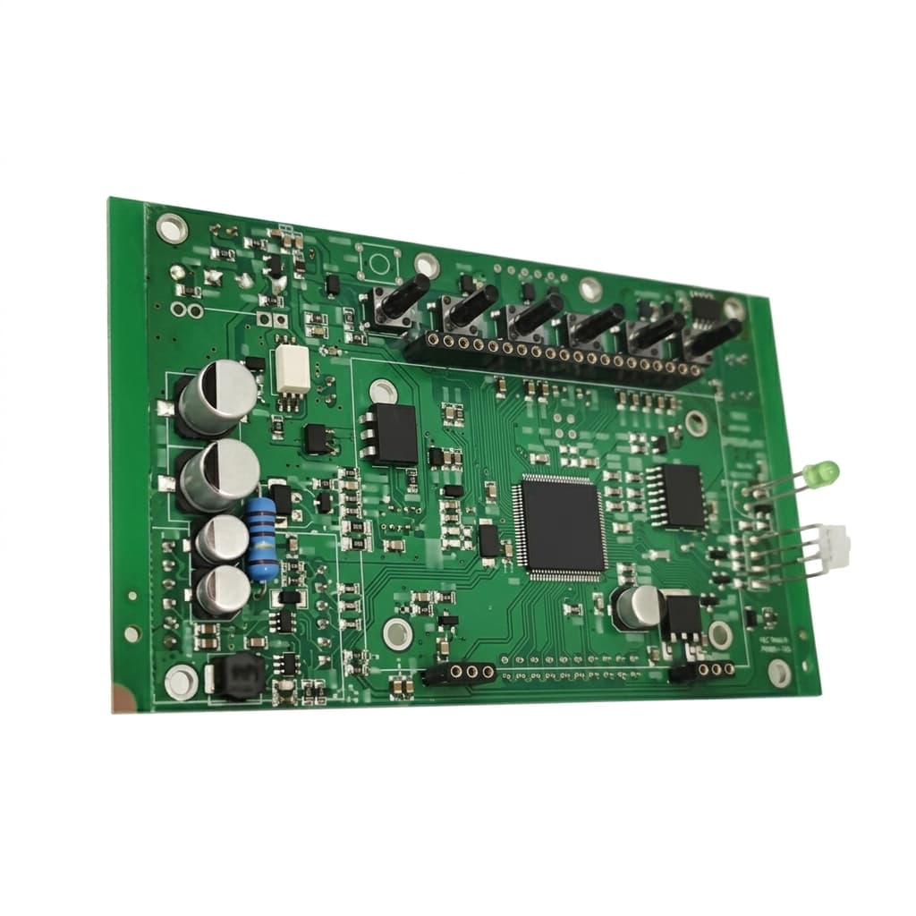
Product image: packaging context only. It does not establish STO implementation, isolation ratings, or certification.
4. Procurement Comparison: External Contactors vs. Integrated STO
Compare like-for-like motor current, DC-bus limits, duty cycle, cooling, required safety functions, and production volume. The following table lists qualification questions, not measured market averages or GAN Servo specifications.
| Evaluation dimension | External contactors + standard inverter | Silicon drive with integrated STO | GaN board with integrated STO | Evidence needed for selection |
|---|---|---|---|---|
| Safety integrity | Depends on complete switching and monitoring architecture | Model-specific declared capability | Model-specific declared capability; GaN gives no automatic advantage | Safety manual, assessment scope, and system calculation |
| Stopping behavior | Bus interruption may leave stored energy and a coasting load | STO alone does not control deceleration | STO alone does not control deceleration | Measured stopping time and required stop function |
| Packaging | Allow for contactors, feedback wiring, and service access | Verify enclosure and heatsink dimensions | Verify board keep-outs, insulation, and heat path | Installed envelope drawing, not bare PCB area |
| Harness mass | Count power, coil, feedback, and safety wiring | Count motor, bus, and safety connections | Include connectors, shielding, and local safety wiring | Weighed assembly BOM at the same boundary |
| Transient immunity | Assess the inverter and control interfaces | Check actual driver and isolator ratings | Check actual switching edges and safety-path immunity | Device limits plus assembled-board test results |
| OSSD compatibility | Match the external safety interface to the controller | Match the specific STO input specification | Match the specific STO input specification | Pulse envelope, wiring rules, and worst-case reaction time |
| Gravity-load holding | Separate brake strategy may be needed | Verify SS1 / SBC availability and brake limits | Verify SS1 / SBC availability and brake limits | Validated brake sequence and load-holding evidence |
| Lifetime and maintenance | Contact wear, monitoring, and replacement interval | Electronic failures and diagnostic assumptions remain | Electronic failures and thermal cycling remain | Mission time, test intervals, and change-control terms |
| Integration cost | Include switching devices, harnesses, and labor | Include drive, cooling, wiring, and validation | Include board, cooling, NRE, fixtures, and validation | Comparable quotes and stated amortization volume |
Reproducible cost worksheet: installed cost per axis = drive + safety interface + harness + thermal/mechanical parts + assembly labor + (NRE and validation cost ÷ production axes). For a hypothetical program with $20,000 of incremental NRE and validation expense over 1,000 axes, amortization alone adds $20 per axis. At 100 axes it adds $200 per axis. These are arithmetic examples, not supplier quotes or evidence that one architecture is cheaper.
5. STO, SS1, and SBC on Gravity-Loaded Axes
STO inhibits torque production; it does not actively brake a moving motor. A horizontal mobile base may coast too far, and a vertical joint may drop under gravity. Neither outcome is acceptable without a validated risk assessment and stopping strategy.
Safe Stop 1 (SS1) combines controlled stopping with subsequent torque removal. Its variant and monitoring requirements must match the selected safety implementation. Safe Brake Control (SBC) provides a safety-related brake control output; it does not by itself establish the mechanical brake's holding capacity, engagement time, wear condition, or diagnostic coverage.
A candidate normal-demand sequence is controlled deceleration, brake application with appropriate confirmation or validated timing, then STO. Fault responses, power loss, failed deceleration, or brake failure may require a different response. Specify the required behavior for each case. An external safety-rated brake controller may be appropriate; integration on the drive board is not universally required.
For design review, document the worst-case stopping distance, gravity load, brake torque margin, brake closing delay, regenerative energy path, restart interlocks, and behavior when the battery cannot accept energy. Verify them with the real motor, gearbox, load, and operating environment.
6. Supplier RFQ Checklist: Seven Evidence Requests
“Designed to comply” is not equivalent to a certified product, but the phrase alone does not prove that no assessment exists. Ask for the evidence and define its acceptance criteria in the RFQ.
- 1. Exact configuration and safety scope: Record part number, hardware/firmware revision, intended safety functions, claimed PL/SIL, and installation limits. If certification is claimed or required by the procurement route, verify the issuing body's certificate and covered configuration. A certificate for a component is not a certificate for the complete drive.
- 2. Quantitative safety evidence: Obtain the safety manual, declared dangerous-failure probability, mission time, diagnostics, and relevant failure-analysis or assessment evidence. Check how the subsystem fits the complete safety function; do not impose a generic PFH, MTTFd, or channel-count threshold without the selected assessment method.
- 3. Transient and safe-state validation: Request relevant CMTI ratings and board-level test conditions, including maximum bus transients, temperature, gate stress, driver supply loss, and identified common-cause faults.
- 4. OSSD and timing compatibility: Compare the actual controller's test-pulse envelope with the accepted drive inputs. Obtain worst-case reaction, discrepancy, reset, and restart timing, then validate the total stopping-time budget.
- 5. Braking and energy handling: Identify who owns SS1, SBC, the mechanical brake, and regenerative energy dissipation. Review stop and power-loss tests at the worst credible speed, inertia, load, and battery charge state.
- 6. Production controls and traceability: Agree inspection coverage, acceptance criteria, end-of-line safety-function tests, serialization, and fault handling. Request PPAP or specific inspection methods when the program requires them; a universal X-ray void limit or burn-in process does not establish functional safety.
- 7. Lifecycle and modification control: Agree availability expectations, product-change notification, safety impact assessment, revalidation ownership, and service replacements. Record contractual commitments rather than assuming a universal semiconductor lifetime or notice period.
For a useful engineering discussion, send GAN Servo the motor data, DC-bus range, board envelope, required safety functions, and target PLr/SIL. Ask which evidence is available for the offered configuration and which validation remains the machine integrator's responsibility.
7. Selection Boundaries: Choose by Hazard and Evidence
Do not assign SIL or PL from robot type, mass, speed, proximity to people, or the presence of fencing alone. Assess each safety function using the machine risk assessment and applicable machinery-specific standards.
- Define the hazard and safe state. Include unexpected startup, coasting, falling loads, electrical energy, and maintenance access. A fenced cell still needs assessed interlocks and stopping behavior.
- Set the required function and integrity. Decide whether torque removal, controlled stopping, safe motion monitoring, or brake control is needed, then establish PLr/SIL through the applicable assessment method.
- Select the complete architecture. An externally switched standard drive may be suitable when the complete circuit, stored-energy behavior, feedback, and diagnostic coverage meet the requirement. Integrated STO may simplify some interfaces but still needs machine validation.
- Release only with an evidence owner. Leave a supplier unqualified where the safety manual, claimed scope, timing, or fault behavior is unresolved. Medical and surgical applications require a separate sector-specific assessment beyond this guide.
8. Frequently Asked Questions
Can ordinary motor-control firmware implement STO by itself?
A normal software stop or PWM-disable command on a non-safety MCU is not an STO claim. A safety implementation may include assessed hardware and software, but it must satisfy the applicable safety lifecycle, fault analysis, and validation requirements. Do not treat one particular two-channel circuit as universally mandated or sufficient.
Does Fail-Safe over EtherCAT (FSoE) replace the drive's safety hardware?
FSoE can carry safety commands over an EtherCAT network when supported by the complete assessed system. It does not make an ordinary EtherCAT drive safety-rated. Check the safety communication endpoints, supported functions, configuration, reaction time, and local torque-inhibition implementation in the product safety manual.
What happens to regenerative energy after STO?
A rotating permanent-magnet motor can still generate voltage. Depending on speed, bus voltage, and the power stage, current may return to the DC link even with switching inhibited. Validate the energy sink when the battery cannot accept charge. A bus capacitor or transient suppressor alone must not be assumed adequate for a full stopping event.
Is a short coast always thermally harmless for GaN devices?
No. Reverse conduction losses and transient stress depend on the exact devices, current, duration, temperature, and circuit. Check the selected datasheets and verify the full stop envelope. Active switching during a demanded STO state must not defeat the safety function.
Do all GaN STO inputs require digital isolators rated above 100 kV/µs?
No universal threshold or isolator technology follows from the GaN label. Select devices against the actual common-mode stress, minimum guaranteed ratings, propagation behavior, and assessed architecture. Qualify the complete safety path under relevant transients rather than approving it from PWM frequency alone.
Does the EU Machinery Regulation mandate SIL 3 / PL e STO for every AI-guided robot?
No. Determine the applicable machine category, safety functions, conformity route, and risk-reduction targets. AI navigation, drive technology, and a drive certificate do not by themselves settle those questions. Keep the safety-related control system's scope and validation responsibilities explicit.
9. Procurement Action Plan
Before freezing the BOM, agree the machine's required safety functions and evidence package. Compare equivalent installed architectures, confirm controller-to-drive compatibility, and allocate brake and regenerative-energy responsibilities. Plan assessment and validation with the responsible teams rather than assuming a fixed certification lead time.
The release decision should answer three questions: Does the configuration meet the required safety function? Is its behavior validated in this machine? Who owns changes and revalidation? Unanswered questions belong on the supplier qualification list, not in an assumed compliance claim.
Sources & References
- European Parliament and Council: Regulation (EU) 2023/1230 on machinery. Use the applicable legal text and transition provisions; an application date is not a universal drive-level SIL/PL mandate.
- International Electrotechnical Commission: IEC 61800-5-2:2016 — Adjustable speed electrical power drive systems, Part 5-2: Safety requirements — Functional. Standard identification and scope; consult the applicable full text and the drive safety manual for implementation requirements.
- International Organization for Standardization: ISO 13849-1:2023 — Safety of machinery, safety-related parts of control systems, Part 1: General principles for design. Design and integration methodology; the public scope does not set application-specific safety functions or PLr.
Source boundary: Public catalogue pages identify the standards and their scope; they are not substitutes for the full normative text, a product certificate, or machine-level validation. The cost and signal examples above are planning calculations, not test results or normative limits.
Author

Categories
More Posts
48V GaN Servo Architecture for Humanoid and AMR Procurement
See why 48V GaN servo drives help humanoid and AMR teams cut harness weight, manage heat, vet suppliers, and request a 48V evaluation kit for pilot sourcing.
AEC-Q101 GaN Servo Drives in Robotics: The 2026 Procurement Guide
Why mobile robotics and AMR buyers are demanding automotive-grade AEC-Q101 GaN servo drives. Compare TCO, lifecycle, and supplier vetting strategies.
BLDC vs. Coreless Motors in Micro Actuators: An Integration Guide
A technical breakdown of when to pair your embedded GaN servo drive with a traditional BLDC motor versus a coreless DC motor for compact robotics.