

Low-Inductance Motors in GaN Servo Drives: Sizing 50kHz–200kHz PWM, Eliminating External Chokes, and Managing Stator Iron Losses in Robotics Procurement
Size GaN servo drives for low-inductance motors: compare 50–200 kHz PWM, estimate ripple, assess iron losses, and use an RFQ checklist. Request pairing review.
Low-inductance motors can benefit from 50 kHz–200 kHz PWM in GaN servo drives, but frequency alone cannot approve a choke-free motor connection. For robotics procurement and motion-control teams, the decision depends on effective winding inductance, allowable RMS and peak current, modulation strategy, motor losses, and the complete drive's thermal limits. Higher frequency can reduce current ripple; it does not guarantee negligible ripple, zero iron loss, or EMC compliance.
Executive Summary (TL;DR)
- At fixed bus voltage, inductance, and modulation, a first-order ripple estimate falls in inverse proportion to PWM frequency: 100 kHz gives one fifth of the 20 kHz estimate.
- Choke removal requires verified motor heating, peak-current margin, current-sensing performance, and controller stability; no universal inductance cutoff applies.
- Stator iron losses depend on the flux waveform and motor construction. A fixed-flux f² relation is not a prediction that total motor losses grow with PWM frequency squared.
- Short dead time can reduce voltage distortion, but the safe setting belongs to the specific switches, gate driver, PCB layout, and operating conditions.
- Use the sizing matrix as a calculation screen, then require a frequency sweep and motor-plus-inverter validation before supplier approval.
Published and reviewed: November 5, 2026. Scope: Global robotics OEMs and automation integrators evaluating 24V–60V DC-input servo drives for low-inductance brushless motors, including slotless and frameless designs. Brushed ironless motors need a different power-stage topology and are discussed only to clarify that boundary.
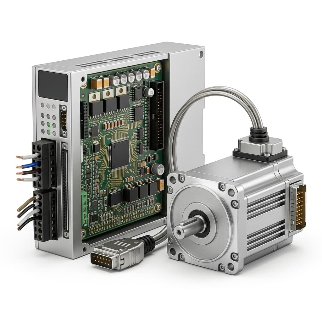
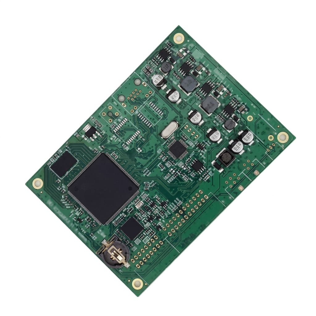
Evidence and calculation limits: This is a procurement guide with illustrative calculations, not a GanServo laboratory report. Reference-design results belong to their named manufacturers and test conditions. The tables do not establish GanServo product ratings or measured customer outcomes. Product images illustrate board form factors; they do not prove choke elimination. Use the motor and drive manufacturers' limits for the final application.
Start with the Low-Voltage GaN Servo Module or Custom Motor Control PCBA Platform, then request a motor-pairing review with your motor datasheet and duty cycle.
1. The Low-Inductance Engineering Bottleneck in Advanced Robotics
Robotic hands, gimbals, surgical effectors, and compact joints often prioritize low rotor inertia and smooth torque. Slotless and ironless winding arrangements can reduce cogging associated with stator teeth, while some compact windings have phase inductance in the single-digit or tens-of-microhenry range. Construction names alone do not establish inductance, acceleration, or torque quality: obtain the winding-specific data.
PWM controls average motor voltage by applying discrete voltage states. A low-inductance winding allows current to change rapidly during each switching interval. The result can be substantial high-frequency current superimposed on the useful torque-producing current, even at standstill. A nominally adequate continuous-current rating does not establish whether the motor and inverter can tolerate the resulting peaks.
A screening estimate, with explicit inductance conventions
For the illustrative calculations in this article, use:
ΔIpp ≈ Vbus / (4 × Leq × fsw)
Here, Vbus is DC-link voltage in volts, Leq is the effective inductance in henries for the modeled PWM current path, and fsw is switching frequency in hertz. ΔIpp is peak-to-peak ripple in amperes. This coefficient is a simplified screening assumption, not a universal worst-case SVPWM phase-current formula. Actual three-phase ripple changes with duty cycle, voltage-vector sequence, electrical angle, back-EMF, saturation, and mutual inductance.
maxon's current-ripple and motor-choke guidance uses this form for specified PWM arrangements and total current-path inductance. Do not transfer its terminal-inductance convention into a phase-current model without checking the topology. A line-to-line value may be approximately twice the phase value for a suitable symmetric star-connected model; delta connections, coupling, and measurement frequency require separate interpretation. Effective inductance at PWM frequency can differ from the datasheet's low-frequency measurement.
Suppose an engineer has established Leq = 10 µH for this simplified model and Vbus = 48 V. At 20 kHz, the estimate is 48 / (4 × 10e-6 × 20e3) = 60 A pp. At 100 kHz it becomes 12 A pp, and at 200 kHz it becomes 6 A pp. These are predictions before current limiting and other nonlinear effects, not claims that a real drive will sustain those waveforms.
For approximately triangular, zero-mean ripple, Iripple,rms = ΔIpp / √12. With a 5 A RMS fundamental current, the 200 kHz example gives 1.73 A RMS ripple and a combined current of √(5² + 1.73²) = 5.29 A RMS. Under a constant-resistance approximation, that is 12% more copper dissipation than the fundamental alone. The 6 A pp ripple is 120% of 5 A, so it cannot reasonably be labeled negligible. Frequency-dependent winding resistance can increase the actual loss further.
2. External Chokes: When Their Mass and Volume Are Justified
Series motor chokes add inductance and can reduce ripple, prevent nuisance peak-current trips, or satisfy a controller's minimum-inductance requirement. They remain a valid option when a higher PWM setting does not satisfy the motor's thermal envelope or the drive's current-sensing and protection constraints.
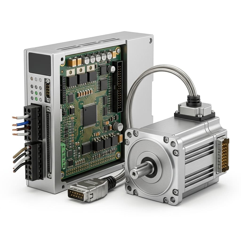
Removing chokes can save their purchased mass, mounting volume, copper loss, and intermediate wiring. The benefit must come from a specific bill of materials. There is no defensible universal gram-per-axis saving, fixed efficiency improvement, or payload multiplier. Wrist mass affects joint torque and inertia through its location and motion; payload consequences require the robot's mechanical model.
| Procurement question | Drive with series motor chokes | Candidate direct GaN connection | Evidence required before selection |
|---|---|---|---|
| Effective inductance | Motor plus relevant series inductors | Motor and interconnect only | Measurement convention, frequency, and current dependence |
| Added mass | Chokes, brackets, and wiring | Integration hardware may still be needed | Weighed assembly and itemized BOM |
| Enclosure volume | Includes choke mounting and clearances | May permit a smaller joint assembly | CAD envelope with cooling clearances |
| Dissipation | Includes choke copper and core losses | Higher PWM can add switching losses | Motor-plus-drive loss map at matching load |
| Interconnections | Additional terminations may be needed | Shorter phase wiring may be possible | Actual harness drawing and serviceability review |
| Current-loop behavior | Choke saturation and impedance affect tuning | Low inductance challenges sensing and timing | Measured loop response and protection captures |
| EMC components | Motor chokes may also affect noise | Other filters can still be necessary | System emissions and immunity measurements |
Treat the comparison as an RFQ worksheet. Ask each supplier to quote both the complete assembly and the validation work. A bare-board quotation can conceal extra cooling, filtering, harness, or firmware costs that determine the final purchasing decision.
3. High-Frequency GaN: A Power-Stage Opportunity, Not a Universal Rating
GaN HEMTs do not have the silicon MOSFET's minority-carrier body-diode reverse recovery. That can reduce a source of commutation loss. Device capacitance, gate-drive power, conduction loss, reverse-conduction intervals, PCB parasitics, and switching overlap still matter. Silicon is not subject to a universal 25 kHz or 40 kHz ceiling, and GaN switching loss is not zero.
A useful published example is TI's TIDA-00909 reference design, whose page describes operation tested to 100 kHz and a peak power-stage efficiency of 98.5% at that frequency. This establishes feasibility for that reference design, not an efficiency guarantee for every motor, operating point, enclosure, or GanServo board.
The EPC9173 quick-start guide describes a three-phase motor-drive switching cell capable of up to 250 kHz with appropriate cooling. Its current capability depends on temperature, voltage, and switching frequency. Procurement must therefore distinguish a switching-cell capability from the continuous system rating with its controller and motor attached.
For a proposed 200 kHz configuration, require the supplier to identify the firmware version, supported continuous current, ambient temperature, housing interface, and derating curve. Verify fault handling at that setting. A configurable PWM register or an unloaded oscilloscope trace is insufficient evidence of a production-ready operating point.
4. Managing Stator Iron Losses Without Misusing the Frequency-Squared Rule
Raising PWM frequency can reduce ripple-related copper and magnetic losses while increasing inverter switching losses. Motor core loss may rise or fall depending on the resulting flux harmonics. Compare the combined motor-plus-drive loss across the intended speed and torque envelope rather than choosing the highest available frequency.
A simplified classical lamination eddy-current relationship is Pe ∝ d² × f² × B², for a given material and sinusoidal flux component within the model's validity. Here, d is lamination thickness, f is that component's magnetic frequency, and B is its flux-density amplitude. Hysteresis, excess loss, skin effects, and nonsinusoidal minor loops require additional treatment.
Holding flux amplitude fixed is the critical condition. PWM flux ripple changes when switching frequency changes; it cannot be assumed constant. The magnetic fundamental follows electrical speed and pole-pair count, not simply the PWM carrier. Consequently, the expression does not establish that changing PWM from 20 kHz to 100 kHz multiplies total stator iron loss by 25.
Thin laminations can reduce one loss component under comparable excitation, but sheet thickness alone does not approve 100 kHz or 200 kHz operation. Request the actual material, construction, loss characterization, and assembled-motor temperature data. Slotless motors may still have a magnetic back iron, conductive rotor components, and magnets that experience harmonic losses; absence of teeth is not absence of all magnetic heating.
| Motor construction | Potential advantage | Remaining concern | Useful supplier evidence |
|---|---|---|---|
| Slotless brushless motor | Reduced tooth-related cogging | Back-iron, rotor, magnet, and winding losses | Frequency sweep with the actual inverter |
| Coreless brushless motor | Reduced iron in the winding region | Low inductance and conductive-component losses | Peak-current and winding-temperature records |
| Thin-lamination frameless motor | Lower classical lamination loss under comparable excitation | Material, flux harmonics, and mounting dominate the result | Material identification and assembled thermal map |
| Conventional slotted BLDC | Established production construction | Tooth harmonics and winding AC resistance | Motor-maker PWM guidance and paired-drive tests |
| High-pole-count torque motor | Compact torque generation | Higher electrical fundamental at a given shaft speed | Pole count, speed range, and loss map |
| Brushed ironless DC motor | Low rotor inertia | Brush/commutator behavior and different drive topology | Compatible H-bridge guidance; outside this three-phase sizing scope |
To isolate PWM effects, hold mechanical speed, useful torque, supply voltage, and cooling conditions constant while sweeping carrier frequency. An unloaded spin test helps reveal some speed-dependent losses, while energized standstill helps screen ripple heating. Neither reproduces the full robot duty cycle or establishes winding hot-spot temperature from a surface image alone.
5. Dead-Time Distortion and Current-Loop Linearity
Each half-bridge needs a blanking interval between complementary switch commands to avoid cross-conduction. Too much dead time can distort applied voltage around current zero crossings; too little can damage the power stage. The safe interval depends on driver delays, switching transitions, layout, temperature, and device variation.
A first-order scale for the dead-time voltage error is |ΔV| ≈ Vbus × td × fsw. The exact coefficient and sign depend on modulation, current direction, and compensation. Reverse-conduction voltage contributes during relevant intervals and must not be added as an unweighted DC offset over the entire PWM period.
For illustration, 500 ns occupies 1% of a 20 kHz period, 5% at 100 kHz, and 10% at 200 kHz. By comparison, 15 ns occupies 0.15% at 100 kHz. These ratios explain the incentive for shorter blanking intervals; they are not complete distortion calculations or universal silicon-versus-GaN specifications.
Require timing measurements and current-waveform captures through zero crossing over the supported bus and temperature range. Do not impose an arbitrary 25 ns setting on every vendor. A stable, validated compensated design is more useful than a smaller unsupported dead-time claim. Encoder accuracy, mechanical transmission, current sensing, and loop tuning still limit low-speed motion quality.
6. Sizing Matrix: Current Ripple across Inductance, Bus Voltage, and Frequency
The following values are reproducible outputs of the Section 1 screening model. Leq is an assumed effective inductance, not an unqualified motor datasheet phase or terminal value. No row is automatically safe, destructive, or approved for direct connection. Values are amperes peak-to-peak, rounded for display.
| Assumed Leq | DC bus | 20 kHz ΔIpp | 50 kHz ΔIpp | 100 kHz ΔIpp | 200 kHz ΔIpp |
|---|---|---|---|---|---|
| 3 µH | 24 V | 100.0 A | 40.0 A | 20.0 A | 10.0 A |
| 5 µH | 24 V | 60.0 A | 24.0 A | 12.0 A | 6.0 A |
| 10 µH | 48 V | 60.0 A | 24.0 A | 12.0 A | 6.0 A |
| 15 µH | 48 V | 40.0 A | 16.0 A | 8.0 A | 4.0 A |
| 25 µH | 48 V | 24.0 A | 9.6 A | 4.8 A | 2.4 A |
| 50 µH | 48 V | 12.0 A | 4.8 A | 2.4 A | 1.2 A |
| 10 µH | 60 V | 75.0 A | 30.0 A | 15.0 A | 7.5 A |
| 20 µH | 60 V | 37.5 A | 15.0 A | 7.5 A | 3.75 A |
Turn an allowable ripple into a frequency or choke requirement
First agree an allowable ripple with the motor supplier using RMS heating, instantaneous peak current, and application requirements. There is no universal 10%–15% procurement limit applicable to all motors. Keep peak-to-peak ripple, ripple RMS, fundamental RMS, and peak phase current distinct in the RFQ.
Rearrange the same model as fsw ≥ Vbus / (4 × Leq × ΔIpp,allow). If a project sets a hypothetical 2 A pp budget at 48 V with Leq = 10 µH, the calculation gives 600 kHz. That exceeds this guide's 50 kHz–200 kHz selection range. At 200 kHz the same budget needs 30 µH total effective inductance, leaving a modeled 20 µH shortfall. Map that shortfall to physical chokes using the actual winding connection and PWM model; it is not automatically a per-phase choke specification.
This is a useful reject-or-investigate result. Options include a compatible higher-inductance winding, lower bus voltage where speed requirements permit, a different modulation method, or retained series inductance. If direct connection is mandatory, document why the motor accepts the higher ripple rather than relabeling the result as negligible.
For assistance translating the calculation into an RFQ, send the winding data and operating envelope to GanServo. Include how inductance was measured so the review does not confuse terminal and phase values.
7. System Architecture: External Chokes versus Integrated GaN
The diagram shows connection choices, not measured efficiency, mass, or an EMC-approved assembly:
With series motor chokes:
DC source → inverter → series motor chokes → low-inductance motor
                 ↘ current sensing and protection ↗

Candidate integrated connection, after validation:
DC source → local DC-link network → GaN inverter → motor
                                      ↕
                            current sensing / controller
Other EMC filters and regeneration provisions remain application-dependent.
Short phase wiring can reduce loop area and cable-related coupling, but common-mode paths through the housing, bearings, encoder, and DC supply remain. Integrating the inverter inside a joint also concentrates heat near the motor. Define thermal interfaces and maintenance access before claiming a packaging benefit.
Local ceramic decoupling helps support switching currents. It does not establish that all electrolytic or bulk capacitors can be removed. Size the DC link for source impedance, transient current, regenerative energy, voltage excursions, and ceramic capacitance reduction under DC bias. Choke-free motor wiring does not mean a filter-free or energy-buffer-free system.
8. Eight-Point RFQ and Procurement Checklist
Use these items as evidence requests for the exact motor, board revision, and firmware configuration. Assign an acceptance owner and record unresolved inputs before comparing supplier prices.
- 1. Continuous operating envelope: Obtain supported PWM settings with continuous and peak phase current, DC-bus range, ambient temperature, cooling interface, and frequency-dependent derating. Confirm that the offered sample and production firmware use the same settings.
- 2. Dead-time and switching evidence: Request configured timing, propagation tolerances, compensation method, and measured switching behavior over temperature and load. Accept only settings validated for the supplied power stage.
- 3. Current-sensing and protection margin: Require usable ADC sampling windows, amplifier settling, common-mode transient behavior, current reconstruction limits, and overcurrent response. Check the intended duty-cycle and speed range rather than mandating one sensing topology.
- 4. Motor thermal validation: Request energized standstill, unloaded rotation, and representative loaded duty-cycle tests at candidate frequencies. Record ambient, housing, winding-temperature estimation, sensors, and stabilization criterion. A fixed 30-minute test is insufficient if temperature has not stabilized.
- 5. DC-link and regeneration design: Obtain effective capacitance under bias, ripple capability, transient voltage records, supply absorption limits, and any brake or clamp requirement. Evaluate the complete capacitor network rather than approving a dielectric label alone.
- 6. Ripple calculation and measurement: Require winding connection, inductance measurement conditions, modulation, maximum bus voltage, ripple RMS and peak-to-peak predictions, plus oscilloscope confirmation. Compare total RMS and instantaneous peaks with motor and drive limits.
- 7. Cable, insulation, and EMC conditions: State actual cable length, shielding, grounding, measured edge rate, overshoot, encoder noise, and the motor manufacturer's repetitive-voltage limits. Do not substitute a generic insulation breakdown voltage for a paired-system rating.
- 8. Control and acceptance records: Record PWM frequency separately from current-loop update rate. Require measured loop bandwidth and stability margins, feedback integrity, startup and fault recovery, and a signed acceptance matrix for the intended operating envelope.
9. Frequently Asked Questions for Engineering and Sourcing Teams
Can we retain silicon drives and add external chokes?
Yes. This may be the lower-risk choice when an existing controller is qualified, the chokes satisfy current and thermal limits, and packaging permits them. Compare total installed cost, mass, losses, and validation effort. GaN is an option for system optimization, not a reason to discard a satisfactory architecture.
What happens to a 5 µH equivalent inductance at 48 V and 20 kHz?
The simplified model predicts 120 A pp before protection or nonlinear effects. That flags a pairing requiring careful investigation. Actual behavior may include current-limit trips or a different waveform. Insulation failure, demagnetization, or a specific time to overheat cannot be predicted from these three inputs alone.
Why not increase PWM to 500 kHz or 1 MHz?
Higher frequency can further reduce ripple but increases switching-event count and challenges sensing, pulse width, controller timing, and thermal design. Motor losses also depend on the resulting harmonic spectrum. There is no universal maximum: choose the frequency that meets the validated system envelope and provides a useful overall benefit.
Does a compact GaN assembly automatically satisfy EMC requirements?
No. Shorter phase leads may help, while faster edges can increase common-mode and high-frequency interference. Gate-drive shaping, grounding, shielding, filters, and enclosure design still require assessment. Compliance belongs to the complete configured product and its applicable test requirements; a board photo or semiconductor choice cannot establish it.
Are slotless motors always suitable for 100 kHz PWM?
No. Their inductance, winding resistance, rotor construction, insulation, and cooling still matter. Conversely, a slotted motor is not automatically disqualified by lamination thickness. Obtain motor-maker guidance and compare measured motor-plus-inverter loss and temperature at candidate carrier frequencies.
Does 100 kHz PWM guarantee a 10 kHz current-loop bandwidth?
No. PWM carrier rate, current-loop execution rate, and closed-loop bandwidth are different quantities. ADC timing, computational delay, sensors, plant dynamics, and stability margin constrain the result. Require a measured frequency response. Electrical bandwidth alone does not establish collision-detection or robot safety performance.
Will GaN lower the total purchase cost?
It can if reduced chokes, cooling, assembly work, or volume offset board and qualification costs. It can also cost more. Compare itemized quotations for the same duty cycle and operating envelope, including engineering effort, production testing, service parts, and any retained EMC or regeneration hardware.
Which encoder interface should we specify?
Choose one supported by the controller and required resolution, latency, cable, and noise environment. Differential signaling and suitable shielding can help, including differential incremental encoders. Absolute protocols are not a universal prerequisite; require error-rate and feedback-integrity evidence under switching and fault conditions.
10. Sources and Technical References
Primary-source URLs checked November 5, 2026. The arithmetic and RFQ decision framework above are illustrative engineering analysis. These references do not validate a GanServo motor pairing, universal lamination thresholds, or the table values as hardware measurements.
- Texas Instruments — TIDA-00909, 48V/10A High Frequency PWM 3-Phase GaN Inverter Reference Design for High-Speed Drives. The official overview supports the cited tested PWM frequency and peak reference-design efficiency. Its Design Guide is identified there as TIDUCE7B; use the manufacturer's documented test conditions. TI reference-design page.
- Efficient Power Conversion — EPC9173 Demonstration Board Quick Start Guide, revision 1.0, revised May 23, 2022. See pages 2–3 for conditional switching-frequency capability and current/thermal qualifications; page 4 describes sensing options. This is a motor-inverter reference, not the unrelated EPC9153 power module. EPC9173 official guide.
- maxon Support — PWM power stage: Current ripple & Motor chokes, updated May 22, 2023. Explains the effects of PWM scheme, supply voltage, effective inductance, and load, with a topology-specific ripple rule and motor-choke example. Its controller-specific guidance is not a universal three-phase safety threshold. maxon technical guidance.
11. Commercial Next Steps and Engineering Support
Before requesting production pricing, prepare one motor-pairing packet: winding connection, terminal and phase resistance conventions, inductance measurement conditions, back-EMF constant, continuous and peak current limits, maximum speed, duty cycle, cooling boundary, and cable length. Add your DC-bus minimum, nominal, maximum, and regeneration conditions. Mark missing information as unresolved rather than filling it with nominal assumptions.
Compare the available Low-Voltage GaN Servo Module and Compact Actuator Driver Board, or review the Custom Motor Control PCBA Platform for a joint-specific form factor. Then request an engineering pairing review to discuss supported PWM configurations and sample-test requirements. Agree the evidence and acceptance limits before treating an evaluation sample as approval for production.
Author
Categories
More Posts
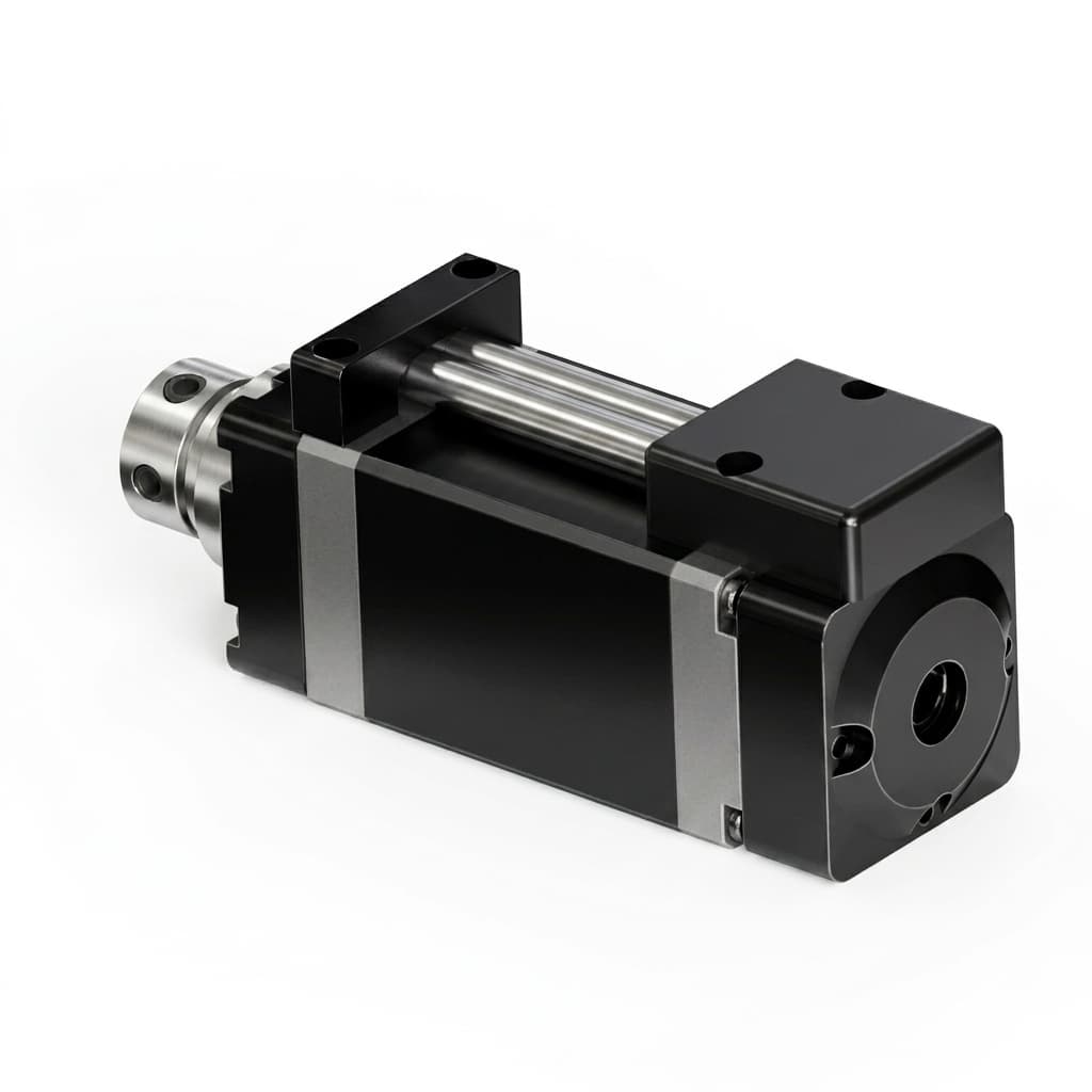
BLDC vs. Coreless Motors in Micro Actuators: An Integration Guide
A technical breakdown of when to pair your embedded GaN servo drive with a traditional BLDC motor versus a coreless DC motor for compact robotics.

GaN vs. Silicon Servo Drives in Mobile Robotics: A Procurement Cost-Benefit Analysis
Compare GaN vs. silicon servo drives for mobile robots. Review TCO, battery, thermal, payload, supplier checks, and request a GAN Servo evaluation kit.
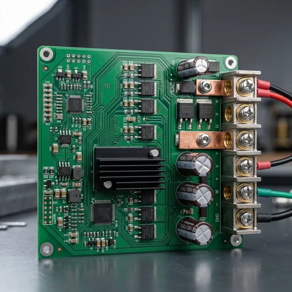
AEC-Q101 GaN Servo Drives in Robotics: The 2026 Procurement Guide
Why mobile robotics and AMR buyers are demanding automotive-grade AEC-Q101 GaN servo drives. Compare TCO, lifecycle, and supplier vetting strategies.